Inductive Current Transformer JGF
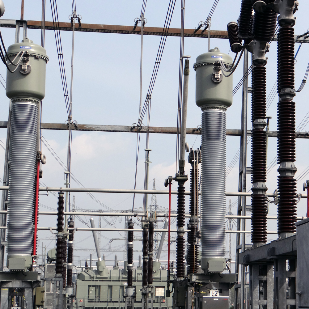
Current transformers type JGF are used in high voltage switchgear within the 245-550 kV range. They transform high current into standardised, equivalent values for meters, measuring and protection devices.

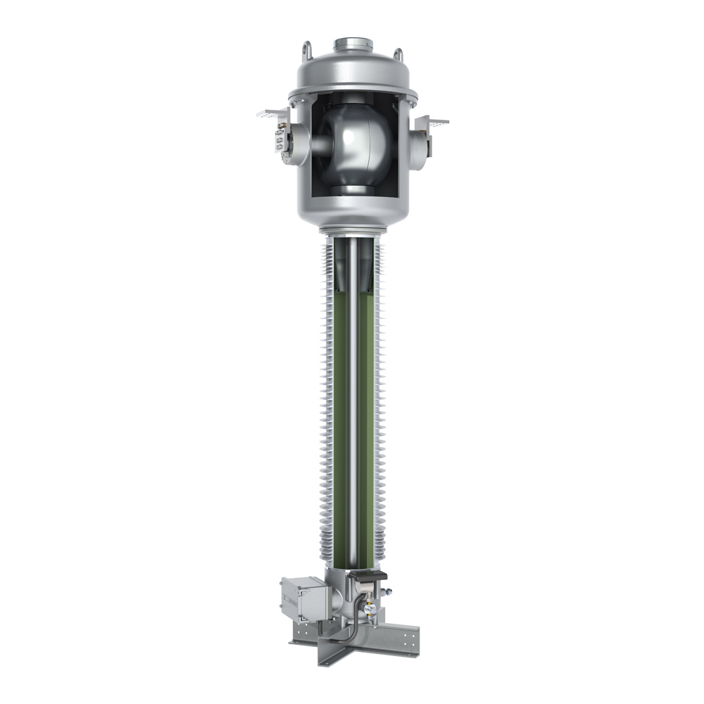
The current transformer section is located in the pressure-resistant head housing. The current transformer cores are fitted in a protective core shell made of massive cast aluminium, which is connected short-circuit proof to the bushing. The secondary outlets are passed through the SF6 /air bushing in the connection terminal box on the base construction of the insulator.
The current distribution along the insulator is optimised by a special layout of the control electrode inside the silicone composite insulator.
The housing components consist of helium-tight, corrosion-resistant cast aluminium. All housing components under pressure are individually typetested according to applicable pressure vessel standards.
The SF6 gas density is monitored temperature-compensated by a gas density monitor with alarm contacts. The special design means the function of the gas density monitor can be checked without dismounting it.
A corrosion-resistant metal rupture disc, protected by a metal cover, located at the top of the head housing ensures safe pressure relief in case of error.
The generously designed terminal box is equipped with a cover that opens sidewards.
Pure SF6 gas is used for ambient temperatures up to -40°C. The transformer is filled with a mixed gas for lower ambient temperatures up to -60°C.

Features
- High operating safety through optimal current distribution in the field-controlled bushing
- Low weight and high creepage resistance through the use of composite insulators
- High flexibility due to simple primary and secondary changeover
- High operating safety through pressure relief with rupture disc


Specifications and Downloads
Technical Specifications
Dimensions

Technical data
Type JGF | 245 | 300 | 330 | 362 | 420 | 550 | |
| Standard | IEC / IEEE | ||||||
| Highest voltage for equipment | kV | 245 | 300 | 330 | 363 | 420 | 550 |
| Rated power-frequency withstand voltage | kV | 460 | 460 | 460 | 575 | 630 | 680 |
| Rated lightning impulse withstand voltage | kV | 1050 | 1050 | 1175 | 1175 | 1425 | 1550 |
| Frequency | Hz | 50 / 60 | |||||
| Primary rated current | A | 5000 | |||||
| Secondary rated current | A | 1 / 5 | |||||
| Rated short-time thermal current [Ith] | kA / 3 s | ≤ 80 | |||||
| Rated dynamic current [ldyn] | kA | ≤ 200 | |||||
| Accuracy class | 0.1-3; P; PR; PX; TPS; TPX; TPY; TPZ | ||||||
| Max. number of CT cores | 8 | ||||||
| Nominal operating / transport overpressure (20°C) | bar | 4 / 0.5 | |||||
Type JGF | 245 | 300 | 330 | 362 | 420 | 550 | ||
| Height of unit* | A | mm | 4197 | 4197 | 5370 | 5370 | 5700 | 6530 |
| Height to primary terminal* | B | mm | 3681 | 3681 | 4730 | 4730 | 5090 | 5890 |
| Depth of unit including terminal box | C | mm | 845 | 845 | 1088 | 1088 | 1088 | 1088 |
| Depth of unit base | D | mm | 749 | 749 | 1088 | 1088 | 1088 | 1088 |
| Width of unit base | E | mm | 436 | 436 | 1075 | 1075 | 1075 | 1075 |
| Distance between screw holes at base | F | mm | 600 | 600 | 900 | 900 | 900 | 900 |
| Min. creepage distance* |
| mm | 6700 | 7500 | 8250 | 9050 | 10500 | 13750 |
| Gross weight, approx.* |
| kg | 670 | 670 | - | - | 1130 | 1200 |
| Gas weight, approx.* | kg | 38 | 38 | - | - | 47 | 50 |
*with standard composite silicone insulator, creepage distance 25 mm/kV