Inductive Voltage Transformer EGF
Voltage transformers type EGF are used in high voltage substations within the 245-550 kV range. They transform high voltage into standardised, equivalent values for meters, measuring and protection devices.

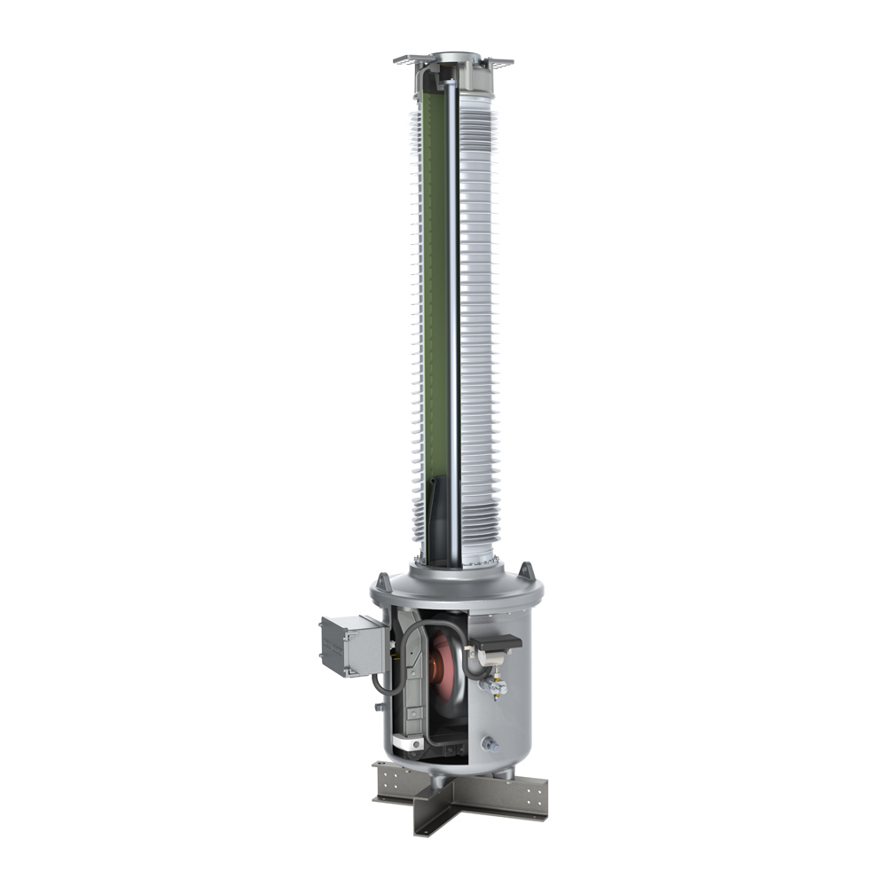
The active section of the voltage transformer is located in the pressureresistant foot housing. The iron core is on earth potential. The secondary windings are directly positioned on the iron core. The secondary windings are passed through an SF6 / air bushing into the terminal box. The high voltage connection is implemented via a short-circuit proof aluminium pipe.
The current distribution along the insulator is optimised by a special layout of the control electrode inside the silicone composite insulator.
The housing components consist of helium-tight, corrosion-resistant cast aluminium. All housing components under pressure are individually typetested according to applicable pressure vessel Standards.
The SF6 gas density is monitored by a temperature-compensated gas density monitor with alarm contacts. The special design means the function of the gas density monitor can be checked without dismounting it.
A corrosion-resistant metal rupture disc, protected by a metal cover, is located at the top of the housing and ensures safe pressure relief in case of error.
The generously designed terminal box is equipped with a cover that opens sidewards.
Pure SF6 gas is used for ambient temperatures up to -40°C. The transformer is filled with a mixed gas for lower ambient temperatures up to -60°C.

Features
- High operating safety through optimised current distribution in the field-controlled bushing
- Low weight and high creepage resistance through the use of composite insulators
- Special iron core provides protection against any ferro resonances


Specifications and Downloads
Technical Specifications
Dimensions

Technical data
Type EGF | 245 | 300 | 330 | 362 | 420 | 550 | |
| Standard | IEC / IEEE | ||||||
| Highest voltage for equipment | kV | 245 | 300 | 330 | 363 | 420 | 550 |
| Rated power-frequency withstand voltage | kV | 460 | 460 | 460 | 575 | 630 | 680 |
| Rated lightning impulse withstand voltage | kV | 1050 | 1050 | 1175 | 1175 | 1425 | 1550 |
| Frequency | Hz | 50 / 60 | |||||
| Accuracy class | 0.1-3; 3P; 6P | ||||||
| Rated thermal limiting output VT part | VA | ≤ 3000 | |||||
| Max. simultaneous burden (cl. 0.2) | VA | ≤ 300 | |||||
| Max. number windings | 5 | ||||||
| Nominal operating / transport overpressure (20°C) | bar | 4 / 0.5 | |||||
Type EGF | 245 | 300 | 330 | 362 | 420 | 550 | ||
| Height of unit* | A | mm | 3930 | 3930 | 4993 | 4993 | 5353 | 6183 |
| Height to primary terminal* | B | mm | 3905 | 3905 | 4968 | 4968 | 5328 | 6153 |
| Depth of unit including terminal box | C | mm | 1052 | 1052 | 1293 | 1293 | 1293 | 1293 |
| Depth of unit base | D | mm | 730 | 730 | 1075 | 1075 | 1075 | 1075 |
| Width of unit base | E | mm | 730 | 730 | 1075 | 1075 | 1075 | 1075 |
| Distance between screw holes at base | F | mm | 600 | 600 | 900 | 900 | 900 | 900 |
| Min. creepage distance* |
| mm | 6700 | 7500 | 8250 | 9050 | 10500 | 13759 |
| Gross weight, approx. * |
| kg | 670 | 670 | 805 | 805 | 820 | 850 |
| Gas weight, approx. * | kg | 21 | 21 | 34 | 34 | 36 | 39 |
*with standard composite silicone insulator, creepage distance 25 mm/kV