Inductive Current Transformer JOF T
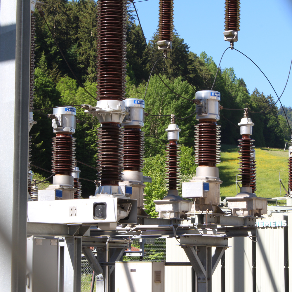
Current transformers type JOF T are used in high voltage networks within the 24-72 kV range. They transform high voltage into standardised values for meters, measuring and protection devices.

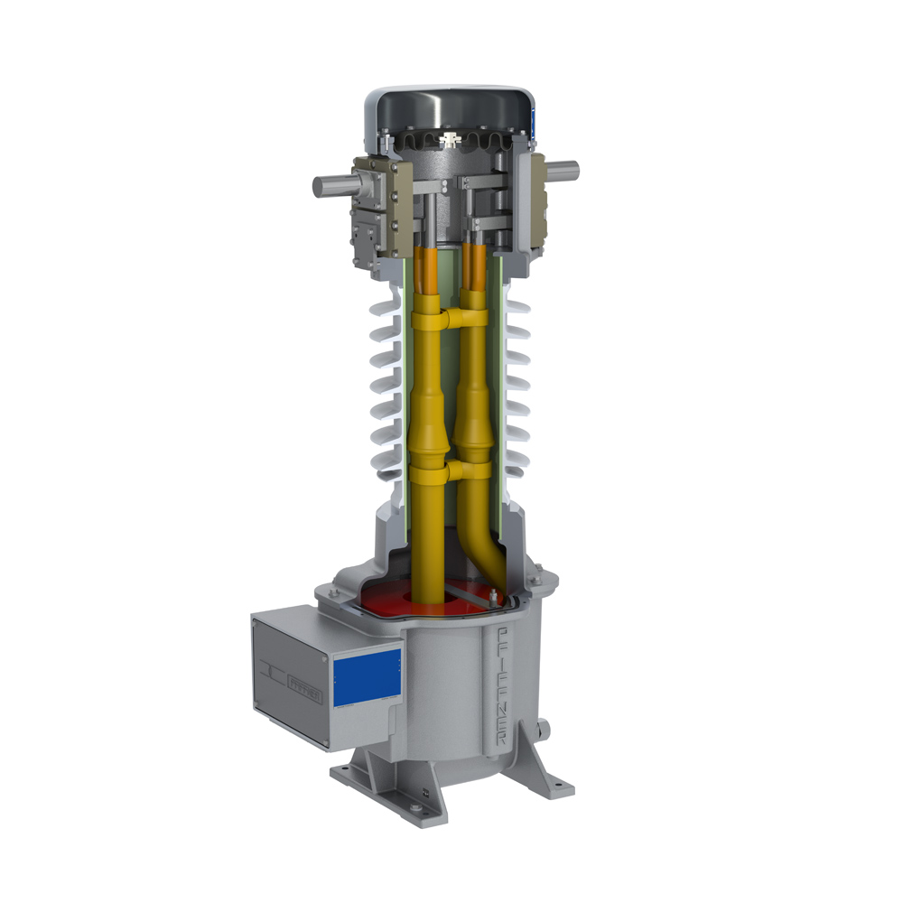
The active part of the current transformer is located in the foot housing. The current transformer is therefore also known under the name tank type or hair pin type. Based on customer specifications, the optimal transformer design is calculated and the current transformer cores in the foot housing are dimensioned.
The high-voltage insulation is made in oil-paper technology. A high-quality PCB-free mineral oil is used for this. The insulated primary conductors are inside the insulator.
The volume compensation of the oil due to temperature fluctuations is guaranteed either by a highly elastic VITON © membrane or by an expansion cell made of stainless steel. The membranes are located in the head part of the current transformer. All metallic housings and flanges are made of a special aluminum alloy. On request, the parts can be painted in different colors.
Depending on the customer's specification, the current transformer is equipped with a high-quality composite or porcelain insulator. Different creepage distances can be selected in accordance with the pollution classes of current standards.
The oil-paper insulation is protected from atmospheric influences by the hermetic closure of the housing.
The generously sized terminal box is equipped with a cover that is to be opened sideways. This allows the secondary cables to be connected more easily. The terminal box is equipped with a blind flange as standard. Cable glands, circuit diagrams and individual safety instructions can be installed on request.

Features
- Oil-paper insulated
- Simple primary winding changeover
- Robust design
- Earthquake-resistant
- Low center of gravity
Specifications and Downloads
Technical Specifications
Dimensions

Technical data
Type JOF T | 24 | 36 | 52 | 72 | |
| Standard | IEC / IEEE | ||||
| Highest voltage for equipment | kV | 24 | 36 | 52 | 72.5 |
| Rated power-frequency withstand voltage | kV | 50 | 70 | 95 | 140 |
| Rated lightning impulse withstand voltage | kV | 125 | 170 | 250 | 325 |
| Frequency | Hz | 16.7 / 50 / 60 | |||
| Primary rated current | A | ≤ 2000 | |||
| Secondary rated current | A | 1 / 5 | |||
| Rated short-time thermal current [Ith] | kA / 1s | ≤ 40 | |||
| Rated dynamic current [ldyn] | kA | ≤ 100 | |||
| Accuracy class | 0.1-3; 0.2S; 0.5S; P; PR; PX; PXR; TPX; TPY; TPZ | ||||
| Max. number of CT cores | 7 | ||||
Type JOF | 24 | 36 | 52 | 72 | ||
| Height of unit* | A | mm | 1386 | 1386 | 1580 | 1580 |
| Height to primary terminal* | B | mm | 1221 | 1221 | 1416 | 1416 |
| Depth of unit including terminal box | C | mm | 668 | 668 | 668 | 668 |
| Depth of unit base | D | mm | 361 | 361 | 361 | 361 |
| Width of unit base | E | mm | 360 | 360 | 360 | 360 |
| Distance between screw holes at base | F | mm | 310 | 310 | 310 | 310 |
| Min. creepage distance* |
| mm | 900 | 900 | 1813 | 1813 |
| Approximate weight* |
| kg | 200 | 200 | 230 | 230 |
*with standard porcelain insulator, creepage distance 25 mm/kV